RTK V6+
six engines plus one support
Auto Verify... Auto Validate...
This vigorous, automated approach to verifying the fixed ambiguities determined by TRIUMPH-LS gives the user confidence in his results and saves considerable time compared to the methods required to obtain minimal confidence in the fixed ambiguity solutions of other RTK rovers and data collectors on the market today. The methods required by other systems are not nearly so automated, often requiring the user to manually reset the single engine of his rover, storing another point representing the original point and then manually comparing the two by inverse, all to achieve a single check on the accuracy of the fixed ambiguities. Acquiring more confidence requires manually storing and manually evaluating more points. Conversely, J-Field automatically performs this test, resetting the multiple engines, multiple times (as defined by user), provides an instant graphic display of the test results, and produces one single point upon completion.
Read details inside and compare with other receivers that require Multiple Point survey, Manual Evaluation, Single Engine, and Single Ambiguity Check per Point.
With TRIUMPH-LS you need Single Point survey, Automated Evaluation, Multiple Engines, and Multiple Ambiguity Checks per Point.
Fundamental in the determination of GNSS solutions is calculating the correct number of full wavelengths (so-called fixing ambiguities) in order to figure out the distances from the satellites to the receiver. In doing Real Time Kinematic (RTK) surveying, we need it fast and we need it to be correct.
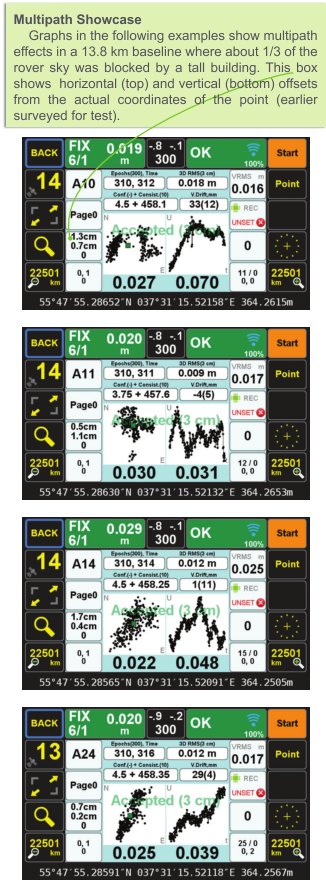
Multipath, the reflections of GNSS signals from ground and nearby objects and structures create their own indirect measurements from the satellites to the GNSS receiver. It’s as if your measuring tape is bent around an obstacle such as a tree instead of a free and clear line of sight between two points. No calculator is going to improve this result.
TRIUMPH-LS has sophisticated hardware to distinguish between the direct and indirect signals and remove most of the indirect signals. It also reports the amount of indirect signal that has been removed. The worst case is when the receiver doesn’t see the direct signal at all; e.g., the satellite is behind a building, but it’s still receiving the signal reflected off of the nearby structure. It is the task of the RTK engines to isolate such indirect signals and then exclude them from the calculations.
If too many of the signals are affected by severe multipath or indirect signals, no solution may be found. Remember, indirect signals are analogous to the bent measuring tape!When you’re preforming RTK surveying, observe your environment and come to recognize that the structures around you are like mirrors for GNSS signals.
The other aspect impacting the veracity of a fixed solution is when there are weak GNSS signals. Frequently, weak signals are due to their penetration directly through tree canopy.
While TRIUMPH-LS can’t move the obstacles that are creating multipath out of the way, its sophisticated hardware has advanced multipath reduction subsystem, its tracking software is designed to handle even the weakest signals, and its J-Field software provides reliable RTK solutions like no other system with its Automatic RTK Verification System (patent pending). J-Filed also has ample tools to demonstrate the reliability of the solution or warn against questionable results. You can readily see that without such tools other systems can provide you wrong and misleading solutions.
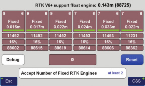
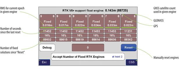
J-Field uses six RTK engines (Figure 1) running in parallel plus a support engine to monitor and aid the six engines. Each engine uses a different criteria and mathematical method tailored to resolve ambiguities in different conditions. These six parallel engines not only verify robust solutions but also maximize the possibility of providing solutions in all conditions.
User Defined Verification Tools
J-Field provides the option for you to specify
the Minimum Number of Fixed RTK Engines
in verifying solutions N times before a position is
automatically accepted where N is a user defined
value.
J-Field employs two metrics to evaluate the
performance of its RTK system of six engines:
1) Confidence Counter, and 2) Consistency
Counter. (Figure 2)
Confidence Counter
This metric is incremented each time an engine is
reset, ambiguities are recalculated, and the solution
is in agreement with the previous ones (as defined
by the Confidence Guard (CG), default value 5 cm)
is achieved. The Confidence Counter increments by
1, 1.25, 1.5, 1.75, 2.0, and 2.5 depending on the
number of reset engines that fix in that epoch.
Consistency Counter
The Consistency Counter is incremented each time a solution is in agreement with the previous ones (as defined by the Confidence Guard) irrespective of engines being reset or not. The Consistency Counter is incremented by 0.0, 0.1, 0.25, 0.5, 1.0 and 1.5 depending on the number of fixed engines used in that epoch. Note that one fixed engine gets no credit and 6 fixed engines gets a Consistency Credit of 1.5.
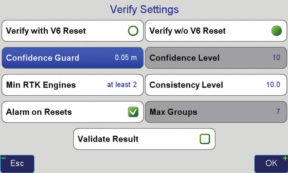
Using these Confidence and Consistency verification tools, J-Field has two options to achieve reliable RTK solutions: 1) Verify With Automatic RTK Engines Resets and 2) Verify Without Automatic RTK Engines Resets.
Verify with Automatic RTK Engines Resets This method has two steps: 1) Confidence Building and 2) Smoothing and verifying.
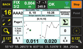
• Step One
In Step One, fixed engines are reset and solutions
are collected into groups. Each group contains all
the epochs located within a specified radius (the CG
value) from its center and new groups are created
as necessary so that all epochs fall into at least
one group. Each group has its own Epoch Counter,
Confidence Level and Elapsed Time. A point may
fall into more than one group. The current best
group is shown within [ ] and others within ( ). Step
One continues until a group reaches the Confidence
Level. (Figure 3)
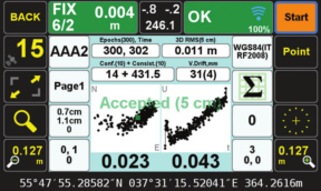
• Step Two
In Step Two, engines are not reset and solutions
which are inside the CG of the selected group are
added to that group for the remaining number of
epochs that user has requested (Epoch Number,
EN). Solutions that are outside the CG of the
selected group, will be ignored but counted and on
each such epoch, the RTK engines will reset. If the
number of ignored points reaches 30% of EN, the
whole process will restart. J-Field has 6 parallel RTK
engines. You can specify the minimum number of
engines required to be fixed to provide an epoch
solution in Step Two. If the number of groups
exceeds the Max Group the process restarts at Step
One. This is to reduce the possibility of creating
too many groups and rare false solutions in difficult
environments. (Figure 4)
In both steps the Consistency Counter is also incremented as mentioned earlier.
You can manually reset all RTK engines via the V6-RTK engines screen (Figure 1), or assign this reset function to any one of the U1 to U4 hardware buttons in front of the TRIUMPH-LS for easy access. Verify without Automatic RTK Engines Resets:
In this method we don’t force the RTK engines to rest but rely mostly on the Consistency Counter. There will be only one group as selected by the first epoch. Solutions that are not within the Guard band of the current average will be thrown out. If more than 30% of solutions are thrown out, the process will restart.
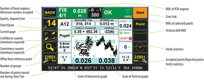
The horizontal and vertical graphs presented in both approaches also help the surveyor to evaluate the final solution. The linear drift of the vertical solution and its drift RMS are also shown above the vertical graph. A high linear drift (more than few centimeters) reveals severe multipath or, in rare cases, a wrong ambiguity fix. Pay close attention to the vertical drift and the horizontal and vertical scatter plots of epochs. Consider the scatter plots as doctors examine X-rays to determine anomalies.
The desired Confidence Level and Consistency Level are user selectable. Default values are 10. These parameters along with the desired number of epochs must be reached before a solution is provided.
In either case there is also a Validate option which, when selected, will reset all engines at the end of the collection and continues with 10 more epochs to validate if the solution is within the desired boundary of the Confidence Guard. (Figure 2) Minimum number of engines for the Validation Phase is user selectable.
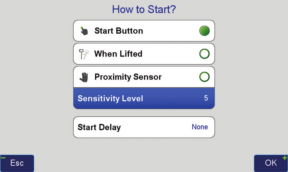
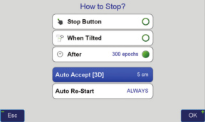
In either case, if Auto-Accept is activated, the position will be automatically accepted if the RMS of the final solution is less than what user has selected in the Auto-Accept screen. (Figure 6)
You can also use Auto-Restart if you want to monitor structures or test the RTK system unattended. (Figure 6)
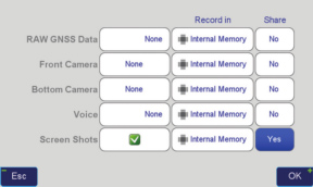
Screen Shots of Action Screen
Action Screen shows detailed information about
each point collected. Screen shots can automatically
be attached to each point and saved at the end of
each collection (Figure 7). In Verify with Automatic
RTK Engines Resets screen shots at the end of
both Step One and Step Two are saved (Figures 3
and 4). In Action screen there are 8 white boxes that
selected items can be viewed on them.
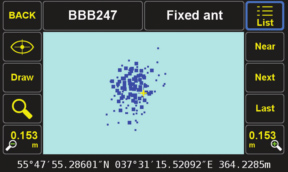
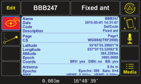
Review Screen
View cluster of all points. Select the desired point
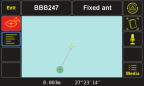
to see its point cluster (Figure 8). Click the icons to
see additional details about that point (Figure 9)
including the distance and direction to the current
point (Figure 10).
The effects of multipath, ionosphere, orbit, and
other sources of problems somewhat exponentially increase as the baseline length increases. In a VRS/RTN scheme your actual baseline length is the actual distance to the nearest base station. The virtual base station that is mathematically created is not the actual length. We strongly recommend using your own base station near your job site in a Verified-Base RTK (VB-RTK) scheme.
In addition to providing you with the most reliable RTK solutions (especially true in remote areas where cell coverage is hit or miss), using your own base receiver allows you to easily tie your solutions to well-established IGS/NGS spatial reference systems through Javad’s exclusive Data Processing Online Service (DPOS) and J-Field’s user-friendly Base/Rover Setup. Note that post-processed results returned to the Triumph-LS using DPOS are dependent on the availability of orbital data from NGS and may require several hours. For further reading about DPOS, its integration into J-Field and the streamlined approach developed by Javad for setting up the base and rover, please check out Shawn Billings’ excellent article on VB-RTK.
Alternatively, if you don’t have access to IGS-type stations to use DPOS, you can select an open area near your job site and use TRIUMPH-LS to obtain its position via RTN networks for about 5 minutes. You may repeat a couple of times for assurance. Then transfer this position to the TRIUMPH-1 or TRIUMPH-2 to use as the base station near your job site. The Base-Rover setup screen in the TRIUMPH-LS makes this job very easy.
Instantaneous Multipath charts
TRIUMPH-LS removes most of the multipath
instantly on every epoch. Click on the Satellite icon
to see the Signal Strength of satellites and then click
the “+” key to see the multipath charts.
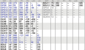
Figure 11 shows the amount of code phase multipath that TRIUMPH-LS has removed; relative to a fixed level. That is why negative numbers are in this figure. Units are in centimeter. Noting the signs in this figure, the amount of multipath in some satellites is in excess of 5.6 meters.
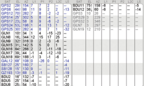
Figure 12 shows the amount of carrier phase multipath that TRIUMPH-LS has removed relative to a fixed level. Units are in millimeter. Noting the signs in this figure, the amount of multipath in some satellites is in excess of 4 centimeters.
Javad Ashjaee, Ph.D.