Specifications
Physical
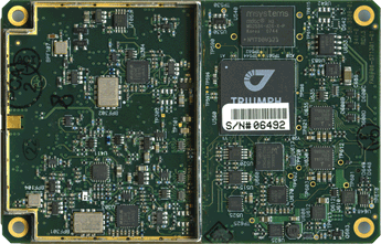
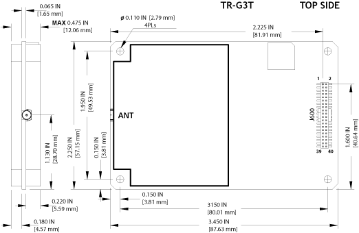
- Dimensions: 57x88 mm
- Weight: 47 g
- Connectors: 2x20 pos, 0.050" pitch for digital, MMCX for antenna
Electrical
- On-board power supply accepts any unregulated voltage between +4.5 to +40 Volts
- Power consumption: 2.5 Watt
Rev. 1 - 4
| Description | Signal Name | Pin # | Pin # | Signal Name | Description |
|---|
| Power Ground | PGND | 1 | 2 | PGND | Power Ground |
|---|
| +4.5 to +40 VDC Power Input | PWR_IN | 3 | 4 | PWR_IN | +4.5 to +40 VDC Power Input |
|---|
| Keep-Alive Power Input for Real-Time Clock (+4.5 to +40 VDC, 10µA typ) | KA_PWR | 5 | 6 | COMMSW# | Active Low Command Input (FN Button) |
|---|
| Active Low input for ON/OFF switch | ONOFFSW# | 7 | 8 | FUO | Factory use only, must be left open |
|---|
| Active Low Reset input | RESET_IN# | 9 | 10 | GND | Signal Ground |
|---|
| Serial port A CTS line | CTSA | 11 | 12 | TXDA | Serial port A TXD line |
|---|
| Serial port A RTS line | RTSA | 13 | 14 | RXDA | Serial port A RXD line |
|---|
| Signal Ground | GND | 15 | 16 | CTSB | Serial port B CTS line |
|---|
| Serial port B TXD line | TXDB | 17 | 18 | RTSB | Serial port B RTS line |
|---|
| Serial port B RXD line | RXDB | 19 | 20 | LED1_GRN | External LED Control |
|---|
| External LED Control | LED1_RED | 21 | 22 | LED2_GRN | External LED Control |
|---|
| External LED Control | LED2_RED | 23 | 24 | IRIG_OUT | IRIG port output line |
|---|
| USB port Power Input line | USB_PWR | 25 | 26 | GND | Signal Ground |
|---|
| USB port D+ line | USB_D+ | 27 | 28 | USB_D- | USB port D- line |
|---|
| 1 Puls Per Second output | 1PPS | 29 | 30 | GND | Signal Ground |
|---|
| Event input | EVENT | 31 | 32 | GPIO0 | Configurable Logic-Level I/O 0 line |
|---|
| Configurable Logic-Level I/O 1 line | GPIO1 | 33 | 34 | GND | Signal Ground |
|---|
| CAN port CAN-H line | CANH | 35 | 36 | CANL | CAN port CAN-L line |
|---|
| RS-422 port TXD+ line | TXDD+ | 37 | 38 | TXDD- | RS-422 port TXD- line |
|---|
| RS-422 port RXD+ line | RXDD+ | 39 | 40 | RXDD- | RS-422 port RXD- line |
|---|
Rev. 5 and later
| Description | I/O | Signal Name | Pin # | Pin # | Signal Name | I/O | Description |
|---|
| Power Ground | | PGND | 1 | 2 | PGND | | Power Ground |
|---|
| +4.5 to +40 VDC Power Input | I | PWR_IN | 3 | 4 | PWR_IN | I | +4.5 to +40 VDC Power Input |
|---|
| Keep-Alive Power Input for Real-Time Clock (+4.5 to +40 VDC, 10µA typ) | I | KA_PWR | 5 | 6 | COMMSW# | I | Active Low Command Input (FN Button)*1 |
|---|
| Active Low input for ON/OFF switch*2 | I | ONOFFSW# | 7 | 8 | FUO | | Factory use only, must be left open |
|---|
| Active Low Reset input*3 | I | RESET_IN# | 9 | 10 | GND | | Signal Ground |
|---|
| Serial port A CTS line | I | CTSA | 11 | 12 | TXDA | O | Serial port A TXD line |
|---|
| Serial port A RTS line | O | RTSA | 13 | 14 | RXDA | I | Serial port A RXD line |
|---|
| Signal Ground | | GND | 15 | 16 | CTSB | I | Serial port B CTS line |
|---|
| Serial port B TXD line | O | TXDB | 17 | 18 | RTSB | O | Serial port B RTS line |
|---|
| Serial port B RXD line | I | RXDB | 19 | 20 | LED1_GRN | O | External LED Control*4 |
|---|
| External LED Control*4 | O | LED1_RED | 21 | 22 | LED2_GRN | O | External LED Control*4 |
|---|
| External LED Control*4 | O | LED2_RED | 23 | 24 | IRIG_OUT | O | IRIG port output line*5 |
|---|
| USB port Power Input line | I | USB_PWR | 25 | 26 | GND | | Signal Ground |
|---|
| USB port D+ line | I/O | USB_D+ | 27 | 28 | USB_D- | I/O | USB port D- line |
|---|
| 1 Puls Per Second output*6 | O | 1PPS | 29 | 30 | GND | | Signal Ground |
|---|
| Event input*7 | I | EVENT | 31 | 32 | GPIO0 | I/O | Configurable Logic-Level I/O 0 line |
|---|
| Configurable Logic-Level I/O 1 line | I/O | GPIO1 | 33 | 34 | GND | | Signal Ground |
|---|
| CAN port CAN-H line | I/O | CANH | 35 | 36 | CANL | I/O | CAN port CAN-L line |
|---|
| Serial Port D: RS232 RTS line or RS422 TX+ line | O | RTSD/TXD+ | 37 | 38 | TXDD/TXD- | O | Serial Port D: RS232 TXD line or RS422 TX- line |
|---|
| Serial Port D: RS232 CTS line or RS422 RX+ line | I | CTSD/RXD+ | 39 | 40 | RXDD/RXD- | I | Serial Port D: RS232 RXD line or RS422 RX- line |
|---|
- *1 Active Low input from the FN button of the MinPad. Internal pull-up 10 kOhm to +3V. Must be left open if not used.
- *2 Active Low input which is equivalent to ON/OFF button of the MinPad. Internal pull-up 10 kOhm to +3V.
For the rev.1 to 4 the pin must be connected to GND permanently if the board is required to turn on automatically any time external power is applied to pins 3 and/or 4.
For the rev.5 and later after abnormal turn off because of external power filure, the boards turn on autmatically when external power is restored.
- *3 Connect to ground to activate. Internal pull-up 2.2 kOhm to +3V.
- *4 LED1_GRN and LED1_RED are used to control the STAT LED of the MinPad. The output is a +3V driver in series with 100 Ohm resistor for each LED. LED should be with common cathode.
- *5 AM sine-wave signal; 2.1Vp-p (Mark), 0.7Vp-p (Space).
- *6 Voh > 2.0V (typ) at 50 Ohm load.
- *7 Internal pull-up 5 kOhm to +3V
Digital connector: Micro Header, 2x20 pos, 0.050″ pitch. Samtec p/n FTSH-120-01-L-DV-K-A.
RF connector: MMCX Jack, edge mount. Amphenol p/n 908-22100. The central pin of the connector is power supply for LNA, +5 VDC with sourced current up to 0.1A.
Environmental
- Operating Temperature: -40°C to +80°C
- Storage Temperature: -40°C to +85°C
- High shock and vibration resistance
|
|